What is an 18650 Battery PCB? A Deep Dive into Safety
Article summerly
The 18650 lithium-ion cellsy is a powerhouse of portablee energy, sustaining whatever from high-performance flashlights to electricly lorries. However, this tremendous power come from inherent dangers if not managed correctlies. This is where the 18650 Battery PCB ends up being the unrecognized hero. This short article supplies a detailed, clinical exploration of this crucial element. We will dissect its function, style, and outright necessity for safe battery operation. Reading this will equip you with the important understanding to utilize 18650 batteries securely and successfully, assisting you understand why secured cells are the remarkable option for nearly every application.
Table of Contents
Abstract
This post supplies an in-depth analysis of the 18650 Battery PCB (Printed Circuit Board), often referred to as a Security Circuit Module (PCM). It details the basic role of the PCB in ensuring the security and longevity of 18650 lithium-ion cells. Secret functions such as overcharge, over-discharge, short-circuit, and overcurrent protection are discussed through a clinical lens. The text analyzes the core electronic components, consisting of MOSFETs and dedicated ICs, that constitute the defense circuitry. Furthermore, it compares protected and unprotected cells, goes over design and screening procedures, and lays out the limitations of these safety systems.
1. What is the Essential Function of a Printed Circuit Board (PCB)?
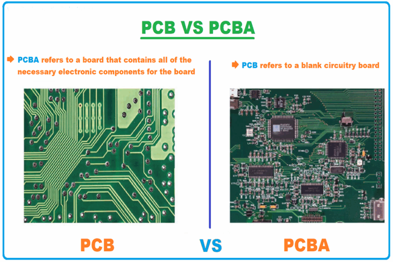
Before we divied into the specifics of battery protection, we must understandly the foundation it is built on. A Printed circuit Board assembly, or PCB, is the bedrock of contemporary electronics. It is a rigid or flexible board made from non-conductive substrate materials like FR-4. Laminated to this substrate are thin layers of copper. A procedure of etching removes unwanted copper, leaving behind conductive pathways or “traces.” These traces form a predetermined circuit, . A PCB’s primary purpose is to offer mechanical support and electrical connectivity for electronic elements. Think of it as a highly arranged and compact city map for electrons. Instead of a messy web of individual wires, a PCB provides a dependable, repeatable, and space-efficient method to build complicated circuits.
2. Why is an 18650 Battery PCB Absolutely Important for Security?
Lithium-ion chemistry, while impressive for its energy density, is volatile. Pressing a cell outside its safe operating specifications can cause disastrous failure. This is not a minor trouble; it can result in venting of flammable gases, fire, and even explosion. The primary objective of an 18650 Battery PCB is to act as a vigilant, always-on manager, preventing the cell from going into these hazardous states. It is a dedicated safety system incorporated straight with the battery.
This little board implements strict operational guidelines. It continuously keeps an eye on the cell’s voltage and the present streaming in and out. If any specification strays from the safe zone, the PCB takes immediate, self-governing action. It digitally disconnects the cell from the circuit, successfully isolating it from the condition triggering the fault. This protective action prevents damage to the battery, the device it powers, and, most notably, the user. Using an 18650 cell without this protection circuit is akin to handling a powerful but unpredictable chain reaction with no security equipment. For that reason, the 18650 Battery PCB is not simply an add-on; it is an indispensable security function.
3. How Does the 18650 Battery PCB Avoid Overcharging?
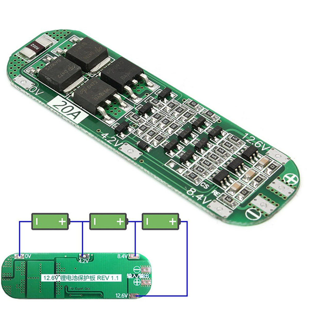
Overcharging is one of the most considerable dangers associated with lithium-ion batteries. A standard 18650 cell has a small voltage of 3.6V-3.7 V and is considered fully charged at 4.2 V.. Metallic lithium deposits on the anode, which can jeopardize the cell’s internal structure, causing an internal short circuit and subsequent thermal runaway . The 18650 Battery PCB provides a robust defense against this situation. It incorporates a devoted defense Integrated Circuit (IC) that exactly keeps track of the cell’s voltage throughout the charging cycle. This IC is programming with a particular overcharge detection voltages, normally between 4.25 V to4.35 V. If the cell’s voltage reaches this threshold, the IC send to a signal to a switchcomponent, typically a MOSFET (Metal-Oxide-Semiconductor Field-Effect Transistor). This MOSFET, functioning as an electronicly gate, instantly opens the circuit, cutting off the flow of current from the battery chargerly.
4. What is Over-Discharge and How Does the PCB Stop It?
Just as overcharging is damaging, so is over-discharging. Draining a lithium-ion cell listed below its minimum safe voltage (typically around 2.5 V) can trigger permanent damage. When the voltage drops too low, the copper existing collector on the anode can dissolve into the electrolyte. Upon recharging, this copper can plate internally, developing dendritic structures that, just like lithium plating, can pierce the separator and cause an internal short circuit. This not only permanently minimizes the cell’s capability but also produces a substantial security risk for future use.
The 18650 Battery PCB actively prevents this damage. The same security IC that keeps an eye on for overcharging likewise expects under-voltage conditions. It has a pre-set over-discharge detection voltage, typically between 2.4 V and 2.75 V. When the gadget in use draws power and the cell’s voltage droops to this lower limitation, the IC activates another MOSFET switch. This switch detaches the cell from the load, stopping any more present drain. While this might power down your gadget suddenly, it is a crucial action that protects the health and safety of the battery cell, enabling it to be recharged safely. An efficient 18650 Battery PCB is crucial for maximizing the cycle life of the cell.
5. Can an 18650 Battery PCB Secure Versus Brief Circuits?
A short circuit is an incredibly harmful event for a high-drain battery. It occurs when the positive and unfavorable terminals are linked directly with a low-resistance conductor, like a roaming piece of metal in a pocket. This develops a course for an enormous and uncontrolled circulation of existing. The battery tries to discharge its whole energy material practically instantly, resulting in quick and severe overheating. This can melt the battery’s housing, spark internal components, and cause a violent failure. The 18650 Battery PCB is crafted with multiple layers of defense versus this danger. The main defense is overcurrent protection. The security IC constantly keeps an eye on the current draw. If the existing exceeds an established safe limit (e.g., 5-8 amps for a basic cell), the IC will journey the MOSFET switch, cutting off the present circulation. For the extreme case of a direct brief circuit, a secondary, quicker mechanism is frequently present. Some PCBs include a PTC (Favorable Temperature Coefficient) thermistor.
6. What Key Elements Make Up an 18650 Battery PCB?
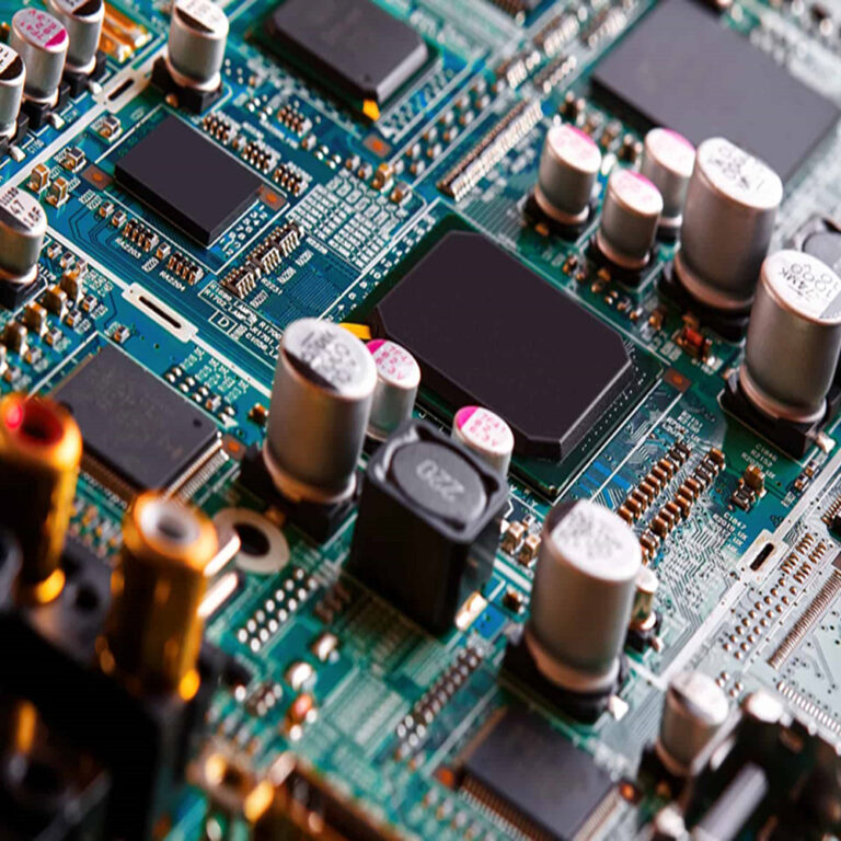
The effectiveness of an 18650 Battery PCB is a direct result of the synergistic function of numerous essential electronic elements. While the board itself is small, it is a center of advanced technology. Understanding these elements provides insight into how the defense system works. The core elements consist of:.
- Defense IC (Integrated Circuit): This is the “brain” of the PCB. This tiny chip is a specialized microcontroller developed for battery management. It houses the reasoning for keeping track of voltage and existing, detecting fault conditions ( overcharge , over-discharge , overcurrent), and controlling the MOSFETs. Popular ICs come from producers like Seiko Instruments, Texas Instruments, and Ricoh.
- MOSFETs: These are the “muscles” or switches of the circuit. Typically, a PCB utilizes two MOSFETs in series– one to manage charging and one to control discharging. When the IC discovers a fault, it sends a signal to eviction of the suitable MOSFET, triggering it to shut off and break the electrical circuit. Their low “on-resistance” is important for minimizing energy loss during regular operation.
- Resistors and Capacitors: These are passive assistance parts. Resistors are utilized to set existing limitations and assist the IC sense existing levels. Capacitors aid to filter out electrical noise and support voltages, guaranteeing the IC can take accurate measurements and avoid incorrect triggers.
- PTC Resistor (Optional): As pointed out, this component provides a resettable “fuse” for overcurrent and short-circuit protection. It provides a physical, temperature-based failsafe in addition to the IC’s electronic monitoring.
Table 1: Secret Components of an 18650 Battery PCB and Their Functions
| Part | Main Function | How It Works |
|---|---|---|
| Protection IC | Brains/Control Center | Continuously monitors cell voltage and present; identifies faults and signals MOSFETs. |
| MOSFETs | Electronic Switches | Act as gates to connect or detach the cell from the battery charger or load. |
| Sense Resistor | Existing Measurement | A low-value resistor utilized by the IC to measure existing circulation by means of voltage drop (Ohm’s Law). |
| Capacitors | Signal Filtering | Support power and signals for the IC, avoiding erroneous readings from sound. |
| PTC Thermistor | Thermal Fuse | Resistance increases drastically with heat from overcurrent, choking the circulation. |
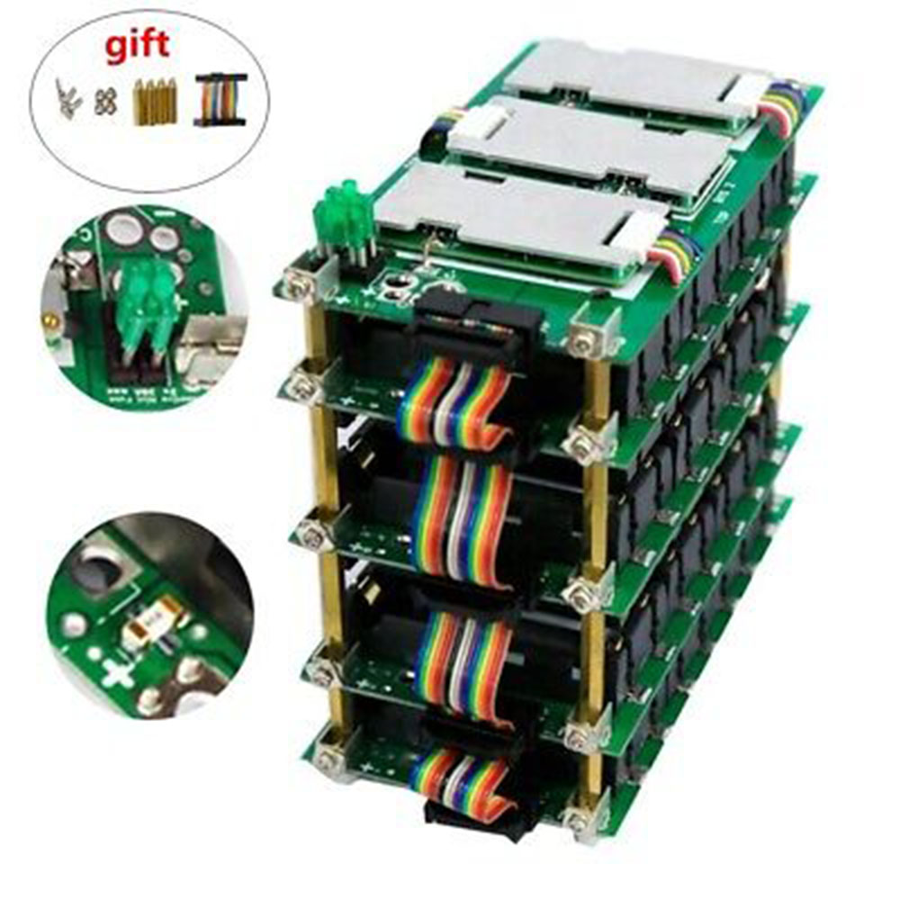
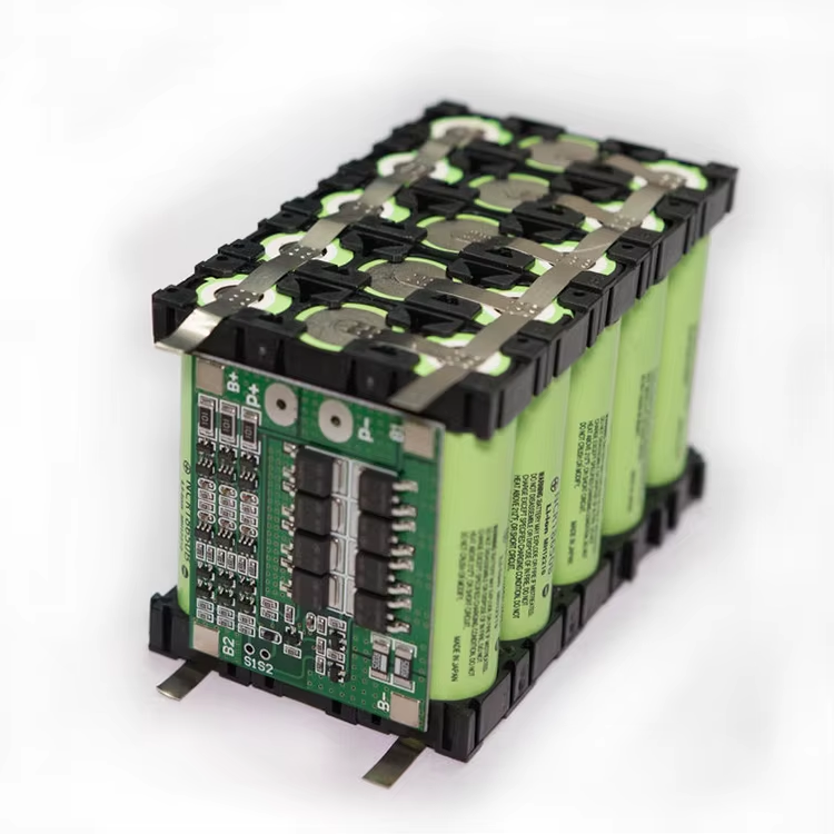
7. Understanding Cell Balancing in a Multi-Cell Load
The role of a protection circuit ends up being a lot more complex and essential in battery packs containing several 18650 cells connected in series. No two cells are ever perfectly similar. Tiny variations in manufacturing result in minor differences in capability and internal resistance. Over many charge and discharge cycles, these small differences cause the cells to end up being out of balance; one cell might be totally charged while another is only at 95%.
If this imbalance is left unchecked, it produces a dangerous situation. Throughout charging, the more powerful cell will reach 4.2 V first and become overcharged while the battery charger continues to press current to charge the weaker cells. During discharge, the weakest cell will strike the 2.5 V cutoff initially and become over-discharged while the pack continues to supply power from the more powerful cells. Advanced protection circuits, often called a Battery Management System (BMS) , which is an advancement of the single 18650 Battery PCB , include a function called cell balancing . The BMS can use passive balancing (bleeding off excess charge from the more powerful cells through resistors) or active balancing (shuttling charge from stronger cells to weaker ones) to keep all cells at an equivalent state of charge.
the Genuine Danger?
The market offers 2 kinds of 18650 cells: safeguarded and unprotected. Unprotected, or “raw,” cells are just the cylindrical cell itself with favorable and negative terminals. Protected cells have an 18650 Battery PCB incorporated, generally at the negative end, making them slightly longer. The distinction in security is significant.
An unguarded cell has no internal safety net. It relies totally on the quality of the charging device and the design of the end-product to prevent overcharge, over-discharge, or brief circuits. If any of these external systems stop working, the cell is susceptible to devastating failure. These cells are planned for usage by skilled manufacturers who build them into custom battery loads that have their own high-quality, external BMS.
A secured cell, by contrast, is a self-contained, safe power source. The incorporated 18650 Battery PCB offers the multiple layers of security we’ve gone over. For the typical consumer, and even for most enthusiast and professional applications, utilizing a protected cell is the only reasonable option. The small additional cost and length are an irrelevant rate to spend for the tremendous increase in safety and assurance.
Table 2: Comparison of Protected vs. Unprotected 18650 Cells .
| Feature | Secured 18650 Cell | Unguarded 18650 Cell |
|---|---|---|
| Safety | High. Integrated 18650 Battery PCB avoids common faults. | Low. No internal security functions. Count on external devices. |
| Secret Part | Includes a Protection Circuit Module (PCM/PCB). | The bare lithium-ion cell only. |
| Length | A little longer (typically 68-70mm). | Standard length (approx. 65mm). |
| Appearance | Typically has a “button top” favorable terminal. | Usually has a “flat top” positive terminal. |
| Expense | Partially higher due to included electronics. | Lower expense. |
| Suitable User | Customers, hobbyists, most commercial products. | Experienced pack contractors, manufacturers with external BMS. |
| Main Threat | The PCB itself can fail, though rare. | High risk of fire/explosion from overcharge, over-discharge, short circuit. |
9. How are 18650 Battery PCB Circuits Designed and Tested?
The reliability of an 18650 Battery PCB is paramount. Credible makers follow an extensive design and screening procedure to ensure their protection circuits work flawlessly under all conditions. The procedure starts with circuit style using CAD (Computer-Aided Design) software application. Engineers set out the traces and component positionings according to a precise schematic designed to satisfy particular voltage and existing limits.
Once the design is completed, it is produced. This involves etching the copper layers, drilling tiny holes for connections, using a non-conductive solder mask (normally the green coating), and screen-printing labels. Components are then mounted utilizing automated pick-and-place makers and soldered into location, often using a reflow oven.
The most critical stage is screening. Every populated PCB undergoes a battery of functional tests to confirm its efficiency:.
- Overcharge Confirmation: The circuit is connected to a cell and charged with a power supply. The voltage is slowly increased past 4.2 V to ensure the PCB cuts off the charge at the correct threshold.
- Over-discharge Verification: The cell is released through a load. The test verifies that the PCB disconnects the load when the voltage drops to its lower limitation.
- Short Circuit Test: The output terminals are intentionally shorted. Testers measure the reaction time and validate the circuit successfully disrupts the huge existing circulation.
- Load Biking: The whole secured cell is executed hundreds or countless charge/discharge cycles to ensure the 18650 Battery PCB carries out reliably over the battery’s lifespan.
- Physical Tension Tests: The unit may go through drop, shock, and vibration screening to guarantee the solder joints and components remain undamaged.
10. What are the Limitations of an 18650 Battery PCB?
While an 18650 Battery PCB is a fantastic safety gadget, it is not foolproof and it is essential to comprehend its limitations. Acknowledging these limitations promotes even more secure battery handling practices.
First, the protection circuit itself consumes a small amount of power. This is called quiescent existing or standby drain. While minimal (determined in microamps), it indicates a protected battery will self-discharge somewhat faster than an unprotected one over a very long storage period.
Second, the defense limits are not infinitely exact. There are producing tolerances. An overcharge cutoff set for 4.25 V may set off at 4.28 V. This is still greatly more secure than having no defense, but it highlights that the PCB is a safety net, not an accuracy lab instrument.
Third, the parts on the PCB, particularly the MOSFETs, have internal resistance. This includes a small amount of resistance to the overall circuit, which can trigger a slight voltage drop and produce a tiny quantity of heat under extremely high loads. For extreme-performance applications requiring optimal present shipment, this can be a factor. The 18650 Battery PCB need to be ranked for the desired present draw.
Finally, the defense circuit is a reactive gadget. It responds to a fault condition that has already begun. When it comes to an extremely violent short circuit, a huge present spike might still occur for a few split seconds before the circuit can react. The very best practice is to constantly prevent the fault condition from happening in the very first location through appropriate handling and usage of quality devices. The 18650 Battery PCB must be considered a critical and obligatory last line of defense.
Frequently Asked Questions (Frequently Asked Questions)
1.What is the main distinction between an 18650 Battery PCB and a BMS?
An 18650 Battery PCB (or PCM) is generally designed to protect a single cell. A Battery Management System (BMS) is an advanced circuit created for multi-cell battery packs. A BMS carries out all the protective functions of a PCB but adds important functions like cell balancing, State of Charge (SOC) computation (fuel assessing), and typically interaction procedures to pass on data to the host device.
2.Does an 18650 Battery PCB affect the battery’s capability or efficiency?
The PCB consumes a minimal quantity of power (quiescent existing) and adds an extremely small amount of internal resistance. For 99% of applications, this impact is undetectable. The immense safety benefits far outweigh the tiny impact on efficiency. However, for ultra-high-drain devices, you need to ensure the PCB is rated to handle the required current.
3.Can I add my own 18650 Battery PCB to a vulnerable cell?
While it is technically possible for specialists with spot-welding devices, it is highly dissuaded for customers and enthusiasts. The process brings a high danger of inadvertently shorting the cell. It is far much safer and more dependable to acquire high-quality, pre-built secured cells from a reputable manufacturer where the 18650 Battery PCB has been expertly set up and evaluated.
4.How can I inform if my 18650 battery has a PCB? .
There are three common signs. First, protected cells are slightly longer (68-70mm) than unguarded cells (65mm). Second, they often have a “button-top” positive terminal, although this is not a universal guideline. Third, if you look closely at the unfavorable terminal end, you can frequently see the edge of the little green or blue circuit board under the cling wrap.
5.What happens if the 18650 Battery PCB fails?
Failure is rare in quality cells however possible. A PCB can stop working “open,” where it completely detaches the battery, rendering it unusable however safe. More precariously, it might stop working “closed” or “shorted,” where the security is bypassed, efficiently turning it into a vulnerable cell. This is why it is vital to buy from relied on brand names that utilize top quality elements and strenuous testing.
Conclusion: The Vital Guardian
The 18650 Battery PCB is far more than an easy device; it is the essential component that makes high-energy lithium-ion cells safe for prevalent usage. It changes a raw, unpredictable chemical cell into a reliable and safeguarded power source.
- It provides robust protection: The circuit vigilantly defends against overcharging, over-discharging, brief circuits, and excessive present.
- It is an integrated supervisor: By utilizing a devoted IC and fast-acting MOSFET switches, it autonomously takes action to prevent catastrophic failure.
- It enables longevity: By preventing harmful over-discharge and managing cell balance in packs, it helps take full advantage of the battery’s functional life expectancy.
- It is the foundation of security: For any application outside of a professionally manufactured battery pack with its own central BMS, utilizing cells with an integrated 18650 Battery PCB is non-negotiable.
When you pick a secured 18650 battery, you are buying a sophisticated electronic security system. This small however effective circuit board is what supplies the confidence and comfort required to harness the incredible potential of modern battery technology.