Mastering PCB design for Military-Grade
Military and defense operations require exceptional strength, not just from workers but from every piece of equipment they rely on. At the heart of this rugged technology lies the printed circuit board (PCB). A failure in a customer device is an inconvenience; a failure in a military system can have disastrous consequences. This guide offers a deep dive into the critical considerations for military-grade PCB design , exploring the products, techniques, and standards that make sure mission-critical reliability. For engineers, designers, and task supervisors, understanding these concepts is not just a best practice– it is a requirement.
Table of Contents
Introduction
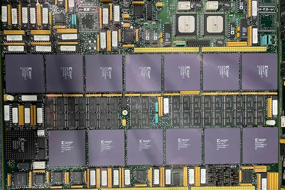
The field of electronics style presents lots of challenges, but couple of are as requiring as military-grade PCB Design . Unlike their commercial equivalents, which are often developed for controlled environments and much shorter lifecycles, military PCBs need to carry out perfectly under the most extreme conditions possible. They face extreme shock, vibration, humidity, and temperature variations. For that reason, the design process must focus on toughness, reliability, and stringent compliance with rigorous requirements from the extremely first concept. This article will function as an extensive guide, covering every aspect of military PCB Design , from preliminary product choice and design strategies to innovative screening procedures and browsing the complex web of required accreditations.
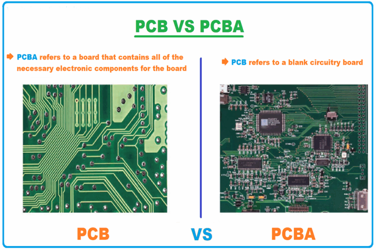
What Genuinely Separates a Military PCB from an Industrial One?
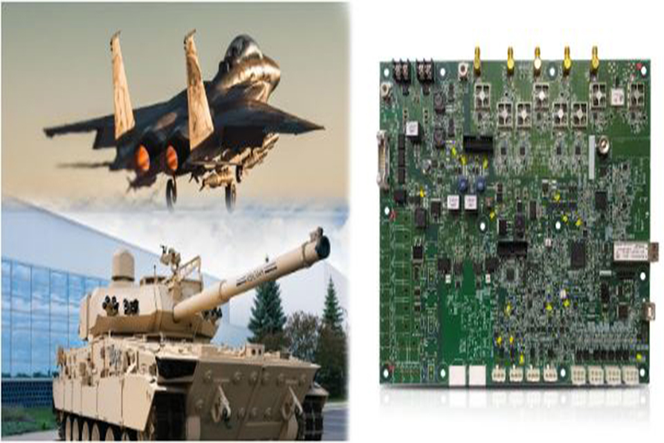
At a surface level, all PCBs share a common purpose: to connect electronic parts. However, the functional requirements for military and commercial applications develop a vast chasm in their design and production viewpoints. Industrial electronics, such as mobile phones or laptops, operate in predictable environments. Producers can use materials and tolerances that balance cost with acceptable efficiency. Military electronic devices receive no such high-end. They must work on a moving armored lorry, in the sub-zero temperatures of the arctic, or the humid heat of a jungle.
This fundamental distinction translates into tangible engineering specs. For instance, a commercial PCB Design may enable part value tolerances of 5-10%. On the other hand, military-grade styles demand much tighter tolerances, typically in the 1-2% range, to guarantee constant performance under tension. The expected item lifecycle likewise differs significantly. While a business gadget might be outdated in a couple of years, military systems are developed for life span of 5 to 15 years, or even longer. This durability requirement influences every decision, from component choice to the option of substrate materials.
To show these differences clearly, think about the following comparison:.
| Feature | Commercial-Grade PCB | Military-Grade PCB |
|---|---|---|
| Operating Environment | Managed (e.g., office, home) | Harsh & unpredictable (severe temps, shock, moisture) |
| Element Tolerance | 5-10% | 1-2% |
| Expected Lifespan | 1-5 years | 5-15+ years |
| Dependability Basic | Great (cost-driven) | Mission-Critical (failure is not an alternative) |
| Compliance | IPC Class 2 | IPC Class 3/A, MIL-PRF-31032, MIL-PRF-55110 |
| Vibration/Shock Resist. | Low to moderate | Really High (ruggedized) |
| Material Requirements | Standard (e.g., FR-4) | High-Tg, metal core, specialized laminates |
| Checking | Standard functional tests | Comprehensive environmental & tension screening (e.g., HALT/HASS) |
Why are Material Choices Foundational in Military PCB Design?
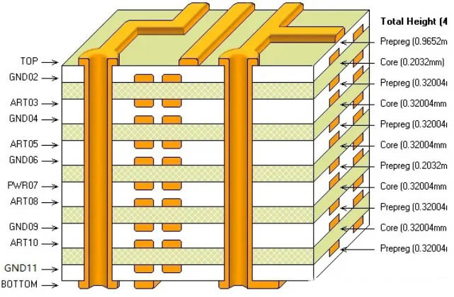
The structure of any robust PCB is its base material, or substrate . For military applications, selecting the ideal product is a non-negotiable primary step. The basic product for many business boards, FR-4 (Flame Retardant 4), is a glass-reinforced epoxy laminate . While affordable and appropriate for many applications, its thermal and mechanical residential or commercial properties are frequently insufficient for military demands. Military systems often create significant heat and operate in high-temperature environments, needing materials with a higher glass transition temperature level (Tg). High-Tg materials can endure higher heat without losing their structural stability.
Engineers often turn to sophisticated composite materials to meet these needs. Some of the most reliable products utilized in military PCB Design include:.
- High-Temperature Laminates: Products like polyimide and specialized epoxy blends provide a much higher Tg than standard FR-4, making sure stability during thermal cycling.
- Metal Core PCBs (MCPCBs): For applications with high-power parts that generate extreme heat, designers utilize PCBs with a metal core, typically aluminum or copper . This metal base functions as an integrated heat sink, efficiently drawing heat away from vital parts.
- Anodized Aluminum: Sometimes, designers use anodized aluminum. This process creates a hard, non-conductive oxide layer on the aluminum surface, which assists avoid oxidation brought on by heat and ecological exposure, further boosting durability.
The option of product straight impacts the board’s rigidity, flexibility, and thermal and electrical efficiency. A deep understanding of product science is therefore indispensable throughout the PCB designphase to make sure the final product fulfills the rigid requirements for military-grade classification.
How Does Advanced Thermal Management Avoid Objective Failure?
Heat is the opponent of electronic dependability. In high-power military systems, such as radar or interactions jammers, reliable thermal management is not simply an optimization– it is a core design requirement. Excessive heat can trigger part failure, break down signal integrity, and reduce the operational life expectancy of the entire system. A sound PCB Design includes several techniques to dissipate heat effectively and preserve steady operating temperature levels.
One typical method is using thermal vias . These are holes drilled through the PCB, often filled with conductive material, that produce a direct path for heat to take a trip from a hot part on the surface area to a larger copper plane or a heat sink on the other side of the board. Another technique includes utilizing heavy copper planes within the PCB’s inner layers. These airplanes function as large, flat heat spreaders, dispersing thermal energy over a larger location and avoiding localized locations.
For the most requiring applications, designers incorporate dedicated heat sinks directly onto the PCB or the enclosure. A thermal interface material (TIM) , such as a thermal paste or pad, is used to fill microscopic air spaces between the component and the heat sink, ensuring effective thermal transfer. The whole thermal method, from through positioning to heat sink choice, must be modeled and simulated throughout the PCB Design stage to verify its effectiveness before producing begins.
What PCB Design Techniques Guarantee Signal Stability?
In a military context, a distorted or lost signal can imply the difference in between objective success and failure. Signal stability refers to the quality of an electrical signal as it takes a trip from a transmitter to a receiver. A poor design can present sound, distortion, and timing errors, rendering a gadget useless. A precise PCB Design design is vital for maintaining signal stability, particularly in boards that mix high-frequency digital signals with delicate analog circuits.
Designers follow numerous essential principles:.
- Element Partition: They physically separate analog and digital elements to avoid high-frequency digital noise from disrupting low-frequency analog signals. Power and ground planes are also typically split to isolate the different circuit sections.
- Managed Trace Geometry: All traces (the copper courses that link elements) are carefully routed. For high-speed signals, designers maintain a specific width and spacing to attain impedance control , which is crucial for avoiding signal reflections. They also keep traces as short and direct as possible.
- 45-Degree Flexes: Sharp 90-degree bends in traces are strictly prevented. At high frequencies, these sharp corners can cause signal reflections and modifications in impedance. Instead, designers use 45-degree bends or curved paths for smoother signal flow.
- Protecting: Vital clock signals and other sensitive traces are typically shielded. This can be done by routing them between ground aircrafts or by running parallel ground traces on either side, a strategy called a “guard trace,” to protect them from electro-magnetic disturbance (EMI).
How Do Element Selection and Installing Methods Enhance Resilience?
A PCB is just as strong as its weakest link. The components soldered to the board and the technique utilized to attach them are important to its general durability. Military systems undergo extreme vibration and mechanical shock, which can cause component results in fracture or solder joints to break. To fight this, the PCB design procedure highlights robust installing methods.
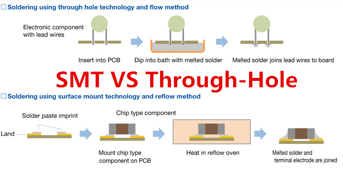
For many years, Through-Hole Technology (THT) has been the preferred method for military applications needing severe sturdiness. In THT, component leads are inserted through holes drilled in the PCB and soldered on the opposite side. This produces an incredibly strong physical bond that can withstand significant mechanical stress. Although Surface Mount Innovation (SMT) allows for greater element density, its solder joints are less mechanically robust. Nevertheless, modern-day techniques like underfill– where an epoxy is applied under an SMT component to strengthen it– are making SMT viable for more rugged applications.
Element choice is equally important. Designers must source components that are particularly ranked for military temperature ranges and have a tested track record of reliability. This typically includes an extensive part sourcing procedure to prevent counterfeit parts and to manage obsolescence, ensuring that replacement parts will be available for the system’s whole 15+ year lifecycle.
What is the Crucial Function of Conformal Coatings and Surface Area Finishes?
A put together military PCB is seldom left exposed to the aspects. To safeguard it from moisture, dust, chemicals, and fungus, a conformal finishing is used. This is a thin, protective polymer movie that “adheres” to the shape of the board and its parts. The option of finishing product depends upon the specific functional environment:.
- Acrylics (AR): Easy to use and fix, using good general security.
- Silicones (SR): Excellent for high-temperature environments and use excellent wetness resistance.
- Urethanes (UR): Provide remarkable resistance to chemicals and abrasion.
In addition to conformal coatings, the surface finish applied to the exposed copper pads on the PCB is crucial. This surface safeguards the copper from oxidation and supplies a solderable surface for element assembly. Typical finishes in military PCB Design consist of:.
- Hot Air Solder Leveling (HASL): A common, low-cost choice, but can lead to uneven surfaces.
- Electroless Nickel Immersion Gold (ENIG): Offers a really flat surface, perfect for fine-pitch parts, and offers excellent rust resistance. This is a popular choice for high-reliability applications.
- Immersion Silver (ImAg): Supplies a really flat, solderable surface area however can be prone to tainting if not dealt with effectively.
What Rigorous Screening Techniques Confirm a Military-Grade PCB design ?
Design and production are only part of the formula. To be accredited for military usage, a PCB should pass a battery of grueling tests that mimic its entire operational life. These tests are developed to find any hidden flaws that could trigger a failure in the field. The main standard for these test methods is MIL-STD-202 .
Key testing phases include:.
- Automated X-ray Evaluation (AXI): This non-destructive test is carried out after assembly. It enables inspectors to see inside the board and check for covert flaws like poor solder connections inside a Ball Grid Range (BGA), spaces in solder joints, and proper alignment of internal layers.
- Functional Checking: This is a basic power-up test to verify the board operates as meant according to its design requirements.
- Environmental Stress Screening (ESS): This is where military PCBs are genuinely put to the test. Boards are put in a thermal chamber and subjected to rapid temperature cycling, typically while being all at once exposed to random vibration. This process, called “shake and bake,” is designed to speed up failures that would otherwise just appear after months or years of usage.
- Extremely Accelerated Life Testing (HALT)/ Highly Accelerated Stress Screening (HASS): These are even more severe variations of ESS, pushing the product beyond its specified functional limitations to find the essential points of failure in the design.
Navigating Accreditations: What are MIL-STD, ITAR, and NADCAP?
The military and aerospace markets are governed by an intricate system of accreditations. It is essential for any OEM or contract manufacturer to comprehend the differences and make sure compliance.
- Military Standards (MIL-STD): These are documents that develop consistent engineering and technical requirements for military-unique or substantially modified commercial procedures, procedures, practices, and methods. Secret requirements for PCBs consist of MIL-PRF-31032 (general requirements for printed boards), MIL-PRF-55110 (for rigid boards), and MIL-PRF-50884 (for flexible boards). They specify the final qualities and performance of the product.
- International Traffic in Arms Laws (ITAR): ITAR is a United States regulatory routine that limits and manages the export of defense- and military-related innovations to protect U.S. national security. It does not just use to complete products; it covers technical data, design details, producing procedures, and repair work treatments. Any company involved in the supply chain for military hardware need to be ITAR certified.
- Nadcap (National Aerospace and Defense Professionals Accreditation Program): While MIL-STD specifies what to develop, Nadcap focuses on how it is built. It is a company-level accreditation program for special procedures utilized in the aerospace and defense markets, such as finishes, heat dealing with, welding, and chemical processing. A Nadcap-accredited manufacturer has shown that its particular processes satisfy the highest market standards.
| Basic | Focus Area | Scope | Function |
|---|---|---|---|
| MIL-STD | Item & Process Specifications | Defines end product attributes, materials, and test methods. | Guarantees interoperability and efficiency of equipment. |
| ITAR | Export Control & Data Security | Controls the export and access to defense-related articles and technical information. | Secures U.S. nationwide security and foreign policy goals. |
| NADCAP | Special Process Accreditation | Audits and recognizes particular business producing processes (e.g., coatings, welding). | Standardizes important procedure control and enhances quality throughout the supply chain. |
How Can You Reduce Supply Chain Risks in Long-Term Projects?
Military programs have remarkably long lifecycles. A system developed today may still remain in service twenty years from now. This durability provides considerable supply chain challenges. A part that is easily offered today might be stopped (end-of-life) in 5 years, making repair work or new production runs difficult. Additionally, the defense market is a prime target for fake elements, which can introduce devastating failures.
A proactive PCB Design method must consist of robust supply chain management. This involves:.
- Careful Part Selection: Choosing components from respectable producers with long-term schedule forecasts.
- Preventing Single-Source Parts: Whenever possible, creating with elements that have numerous “form, fit, and function” replacements from different vendors.
- Life time Purchases: For crucial, single-source elements, the task might require to buy enough stock to last the entire predicted life of the program.
- Partnering with Vetted Suppliers: Working specifically with agreement manufacturers and distributors who have rigorous anti-counterfeit assessment and verification processes in place.
What Are the Future Trends Forming Military Electronics?
The field of military PCB Style is continuously evolving to fulfill new battlefield demands. Key trends consist of:.
- Miniaturization (SWaP): There is a constant drive to reduce the Size, Weight, and Power (SWaP) of military electronics. This presses designers towards higher-density interconnects (HDI), smaller sized components, and more complex, multi-layer board styles.
- Rigid-Flex PCBs: These boards combine stiff areas with flexible interconnects, enabling them to be folded and bent to suit compact, irregular spaces. This is ideal for wearable innovation, rockets, and avionics, eliminating the requirement for bulky ports and cable televisions.
- Greater Frequencies: The move towards advanced radar, satellite interactions, and electronic warfare systems requires PCBs that can handle incredibly high frequencies (RF/microwave). This requires using specialized substrate products with low signal loss and advanced layout techniques to manage EMI and signal integrity.
Frequently Asked Concerns (Frequently Asked Questions)
What is the primary distinction in between industrial and military PCB design?
The primary difference depends on the style viewpoint. Industrial PCB designbalances expense and efficiency for controlled environments, while military PCB designprioritizes severe reliability, toughness, and a long life span in severe, unpredictable conditions, frequently with expense as a secondary issue.
Why is Through-Hole Technology (THT) frequently chosen for military applications?
THT creates a stronger mechanical bond between the element and the board due to the fact that the element leads pass through the board and are soldered on both sides. This makes the assembly highly resistant to the extreme shock and vibration common in military environments.
While possible for some non-critical, ground-ba?
sed applications in controlled environments, it is generally not recommended. Military applications generally require materials with a higher glass transition temperature level (Tg), like polyimide or other advanced laminates, to handle the extreme temperature levels and thermal biking without jeopardizing structural stability.
What is ITAR and why is it important for PCB manufacturers? .
ITAR (Global Traffic in Arms Laws) is a set of U.S. federal government guidelines that control the export and import of defense-related posts and services. Any business involved in the style, production, or handling of military PCBs should be ITAR compliant to prevent delicate technology from falling into the wrong hands.
How do you typically evaluate a military-grade PCB?
Military PCBs go through a series of rigorous tests, consisting of Automated X-ray Assessment (AXI) to find surprise solder defects, functional testing to guarantee they work, and Environmental Tension Screening (ESS), where boards go through quick temperature level modifications and vibration to force hidden failures to appear.
What is a conformal finishing and why is it used?
A conformal finishing is a thin, protective polymer film used to a fully put together PCB. It safeguards the delicate electronic elements from moisture, dust, chemicals, and other ecological pollutants that might cause a brief circuit or corrosion, thereby increasing the dependability and life expectancy of the board.
Conclusion: Secret Takeaways for Robust PCB Design
Creating a printed circuit board for military applications is a discipline of accuracy, insight, and uncompromising quality. It extends far beyond the basic plan of components on a board. Every choice, from the choice of a substrate to the application of a conformal covering , straight affects the end product’s capability to perform under pressure and conserve lives. Success in this demanding arena requires a holistic technique that integrates product science, thermal engineering, signal stability analysis, and strenuous screening into every stage of the PCB Style process.
Here are the most crucial things to bear in mind:
- Focus on Reliability Above All: The core viewpoint of military PCB Style is to produce items that will not stop working, even in the harshest environments.
- Product Choice is Vital: Utilize high-Tg laminates, metal cores, and other innovative materials to withstand thermal and mechanical tension.
- Manage Heat Strongly: Employ thermal vias, copper planes, and heat sinks to guarantee parts run within safe temperature limits.
- Layout for Signal Integrity: Separate digital and analog areas, utilize controlled impedance traces, and avoid sharp bends to make sure clean signals.
- Embrace Toughness: Favor long lasting mounting strategies like THT and select parts particularly ranked for military usage.
- Test, Test, and Test Again: Use a combination of AXI, functional, and environmental stress screening to validate the style and discover latent defects.
- Make Sure Complete Compliance: Understand and comply with all relevant requirements, consisting of MIL-STD, ITAR, and Nadcap, by partnering with certified producers.
By adhering to these principles, engineers can with confidence develop the high-reliability electronics that form the backbone of modern-day defense innovation.